Lesson 1
-
The goal of these threads is to teach students English and Microcontroller Programming by posting short tasks and solutions.
To run and compile programs you should use IDE.
You can download SimulIDE (to simulate circuits)
(Link1) https://launchpad.net/simulide
(Link2) https://www.simulide.com/p/downloads.html
Recommended version is SimulIDE_1.1.0-RC1_Win64 (or any other version >=1.1.0).Atmel Studio (to use avrasm) (recommended version Atmel Studio 6.0)
(Link1) https://atmel-studio.software.informer.com/6.0
(Link2) https://www.google.com/search?q=Atmel+Studio+6.0WinAVR (to use C)
WinAVR-20060421-install.exeArduino IDE (to use arduino)
https://support.arduino.cc/hc/en-us/articles/360019833020-Download-and-install-Arduino-IDE -
Unzip and copy a downloaded SimulIDE to your working place ("Local Disk C" for example). Let's name it as "SimulIDE".
Install Atmel Studio 6.0 to your working place ("Local Disk C:\Program Files" for example).
Install WinAVR to your working place ("Local Disk C" for example).
Install Arduino IDE to your working place ("Local Disk C" for example).Find the folder "avrassembler" in "C:\Program Files\Atmel\Atmel Studio 6.0\extensions\Atmel\AVRAssembler\2.1.51.64" and copy this folder.
Create the new folder "my-avr" in "C:\SimulIDE\examples\Micro" and paste the folder "avrassembler" to there.Create the new folder "Arduino" in "C:\Users\YourUsername\Documents" (YourUsername is your name) and copy all files from "C:\arduino-1.8.18" to there.
If you want to make an AVR project with avrasm or C then you should go to the folder "C:\SimulIDE\examples\Micro\my-avr"
From now on whenever you want to make an own project with an AVR microcontroller you should do the following:
A.Create a new project folder in the directory "my-avr".
B.Create the subfolder "gcb_code" in the project folder.
C.Make a circuit and save it to your project folder.
D.Add a simulation program to your project.
E.Set correct Compiler Settings.
Avrasm2
Avrgcc
If you want to make Arduino project then you should go to the folder
"C:\SimulIDE\examples\Micro\my-avr"
From now on whenever you want to make an own project with an Arduino microcontroller you should do the following:
A.Create a new project folder in the directory "my-avr".
B.Create the subfolder "yourprojectname_ino" in the project folder. .
C.Make a circuit and save it to your project folder.
D.Add a simulation program to your project. -
We will make all our avr projects with ATmega168. ATmega168 is often used as a main chip in Arduino boards.
Let's make our first project.
Blinking LED in AVR Assembler.
Create the folder "blinking-led-avr-asm" in the directory "my-avr".
Create the subfolder "gcb_code" in the folder "blinking-led-avr-asm".
Find the file "m168def.inc" in "C:\SimulIDE\examples\Micro\Avr\my-avr\avrassembler\include". Copy this file.
Paste "m168def.inc" to the folder "C:\blinking-led-avr-asm\gcb_code".
Open the program SimulIDE and click "Save Circuit As", then save your project to the folder "blinking-led-avr-asm\gcb_code" with the file name "blinking-led-avr-asm".
Find (you can type a name of a component in the field "Search Components" or search a component by browsing Categories of Components in the left menu), drag and drop on Form the next components:
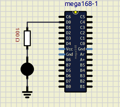
mega168 (Micro->AVR->atmega->mega168)
resistor 100 Ω (Passive->Resistors->Resistor)
Led (Outputs->Leds->Led)
Ground (0 V) (Sources->Ground (0 V)).
You can zoom in/zoom out your working area by using a scroll wheel.
Connect all components with wires in the same way, as in the picture. You can rotate a component by right-clicking a component and clicking "Rotate CW/Rotate CCW" a few times. The resistor must be connect to D0. Pay attention to LED, since it emits light only if it's connected correctly. The current must go from an anode to a cathode (LED will not emit light if you connect it in the opposite direction).
Click "Save Circuit".
It's time to add the code to our program. -
1);*******************************************************
2);Chip Model: MEGA168
3);Assembler header file
4).INCLUDE "m168def.inc" ;tells the AVR assembler to add the contents of a file to our program
5);*******************************************************
6).ORG 0 ;indicates the beginning of the address; puts our code at the beginning of flash memory
7)
8);The next block initializes the SP to point to the last location of RAM (RAMEND),
9);(set up stack)
10).MACRO INITSTACK ;macro AVR assembler
11)LDI R20, HIGH(RAMEND) ;loads R20 with the high byte of RAMEND
12)OUT SPH, R20 ;initializes SPH
13)LDI R20, LOW(RAMEND) ;loads R20 with the low byte of RAMEND
14)OUT SPL, R20 ;initializes SPL
15).ENDMACRO ;macro AVR assembler
16)
17)INITSTACK ;macro AVR assembler
18)
19)SBI DDRD,0 ;makes PD0 an output port
20)BACK:
21)SBI PORTD,0 ;turns on PD0
22)RCALL DELAY ;time delay, calls the DELAY subroutine
23)CBI PORTD,0 ;turns off PD0
24)RCALL DELAY ;time delay, calls the DELAY subroutine
25)RJMP BACK ;jumps to BACK, keeps doing it forever (an infinite loop)
26)
27)DELAY:
28)LDI R20, 100 ;loads R20 with the value 100 in dec
29)L0: LDI R21, 250 ;loads R21 with the value 250 in dec
30)L1: LDI R22, 250 ;loads R22 with the value 250 in dec
31)L2:
32)NOP ;does nothing (1 Instruction cycle)
33)NOP ;does nothing (1 Instruction cycle)
34)DEC R22 ;decrements R22 by one, assign Z:=1 if R22==0 (1 Instruction cycle)
35)BRNE L2 ;tests the zero flag (Z), branch to L2 if Z==0 (2 Instruction cycles)
36)DEC R21 ;decrements R21 by one, assign Z:=1 if R21==0
37)BRNE L1 ;tests the zero flag (Z), branch to L1 if Z==0
38)DEC R20 ;decrements R20 by one, assign Z:=1 if R20==0
39)BRNE L0 ;tests the zero flag (Z), branch to L0 if Z==0
40)RET ;returns to caller (the end of the DELAY subroutine)
41);*******************************************************
42);COMMENTS
43);Let's calculate the time delay of the DELAY subroutine. You can find the crystal frequency of atmega168 by right-clicking the component atmega168 on Form and clicking Properties.
44);It's 16 Mhz by default. So instruction cycle = 1/16 MHz = 0.0625 μs = 62.5 ns (nanosecond).
45);We have 100 loops, 250 loops, 250 loops.
46);Delay=100 * 250 * 250 * (1+1+1+2) * 62.5 ns=1,953,125,000 ns=1,953,125 µs≈2 s.
47);The time delay is not precise, since we have not included the overhead associated with the two outer loops.The program has the next flow chart
Initialization (1-17)
------|---------------
Make PORTD0 an output port (19)
------|---------------
BACK:
Main program (21-24)
go to BACKYou can copy-paste the Initialization block to every AVR assembler program without thinking, since it's the same for every program.
SBI DDRD,0 ;makes PD0 an output port
DDRD has 8 bits (bbbbbbbb).
We set bit 0 of DDRD to 1 (bbbbbbb1).
This setting makes PORTD0 an output (it can be input also).SBI PORTD,0 ;turns on PD0
RCALL DELAY ;time delay, calls the DELAY subroutine
CBI PORTD,0 ;turns off PD0
RCALL DELAY ;time delay, calls the DELAY subroutineSBI (Set Bit in I/O register)
CBI (Clear Bit in I/O register)
It's the main part of our program. This block of the code turns on and turns off our LED with delay 2 seconds.DELAY subroutines makes 2 seconds delay. We make delays by looping 100 * 250 * 250 times (it takes time to run those loops for AVR and keeps the microcontroller busy for 2 seconds).
-
;******************************************************* ;Chip Model: MEGA168 ;Assembler header file .INCLUDE "m168def.inc" ;tells the AVR assembler to add the contents of a file to our program ;******************************************************* .ORG 0 ;indicates the beginning of the address; puts our code at the beginning of flash memory ;The next block initializes the SP to point to the last location of RAM (RAMEND), ;(set up stack) .MACRO INITSTACK ;macro AVR assembler LDI R20, HIGH(RAMEND) ;loads R20 with the high byte of RAMEND OUT SPH, R20 ;initializes SPH LDI R20, LOW(RAMEND) ;loads R20 with the low byte of RAMEND OUT SPL, R20 ;initializes SPL .ENDMACRO ;macro AVR assembler INITSTACK ;macro AVR assembler SBI DDRD,0 ;makes PD0 an output port BACK: SBI PORTD,0 ;turns on PD0 RCALL DELAY ;time delay, calls the DELAY subroutine CBI PORTD,0 ;turns off PD0 RCALL DELAY ;time delay, calls the DELAY subroutine RJMP BACK ;jumps to BACK, keeps doing it forever (an infinite loop) DELAY: LDI R20, 100 ;loads R20 with the value 100 in dec L0: LDI R21, 250 ;loads R21 with the value 250 in dec L1: LDI R22, 250 ;loads R22 with the value 250 in dec L2: NOP ;does nothing (1 Instruction cycle) NOP ;does nothing (1 Instruction cycle) DEC R22 ;decrements R22 by one, assign Z:=1 if R22==0 (1 Instruction cycle) BRNE L2 ;tests the zero flag (Z), branch to L2 if Z==0 (2 Instruction cycles) DEC R21 ;decrements R21 by one, assign Z:=1 if R21==0 BRNE L1 ;tests the zero flag (Z), branch to L1 if Z==0 DEC R20 ;decrements R20 by one, assign Z:=1 if R20==0 BRNE L0 ;tests the zero flag (Z), branch to L0 if Z==0 RET ;returns to caller (the end of the DELAY subroutine) ;******************************************************* ;COMMENTS ;Let's calculate the time delay of the DELAY subroutine. You can find the crystal frequency of atmega168 by right-clicking the component atmega168 on Form and clicking Properties. It's 16 Mhz by default. So instruction cycle = 1/16 MHz = 0.0625 μs = 62.5 ns (nanosecond). ;We have 100 loops, 250 loops, 250 loops. ;Delay=100*250*250*(1+1+1+2)*62.5 ns=1,953,125,000 ns=1,953,125 µs≈2 s. ;The time delay is not precise, since we have not included the overhead associated with the two outer loops. -
Create a new code file in SimulIDE. Copy-paste the program to the code window of SimulIDE (you may click the button Select All (from the previous post) and press Ctrl+С (to copy the code from the forum) and Ctrl+V (to paste the code)).
Click "Save". Then enter "File name: blinking-led-avr-asm", select "Save as type: Asm(*.asm)" and click "Save" in the pop up window "Save Document As".
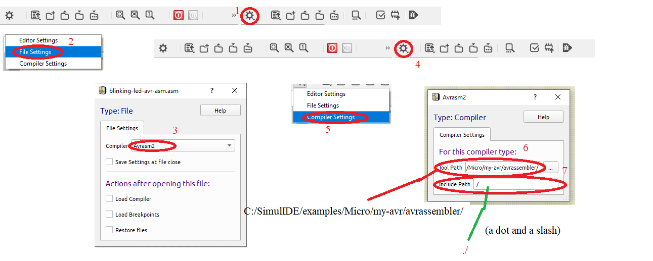
Click the gear wheel button "Settings" and click "File Settings".
Now select "Compiler: Avrasm2",
Click the gear wheel button "Settings" and click "Compiler Settings".
Click "Select tool path" and browse to "C:\SimulIDE\examples\Micro\my-avr\avrassembler" (or your path), click "Select Folder",
"Include path: ./".
Then close "Compiler Settings" window.
Click "Compile", then click "UpLoad".
You should see "Assembly complete, 0 errors. 0 warnings" when everything is OK.
Whenever you want to edit a code you have to click the next buttons after changes: "Compile" and "UpLoad".
Then your program will work correctly.
Click the red button "Power Circuit".
You should see a blinking LED. -
Blinking LED in AVR GCC.
Create the folder "blinking-led-avr-c" in the directory "my-avr".
Create the subfolder "gcb_code" in the folder "blinking-led-avr-c".
Open the program SimulIDE and click "Save Circuit As", then save your project to the folder "blinking-led-avr-c\gcb_code" with the file name "blinking-led-avr-c".
Find (you can type a name of a component in the field "Search Components" or search a component by browsing Categories of Components in the left menu), drag and drop on Form the next components:
mega168 (Micro->AVR->atmega->mega168)
resistor 100 Ω (Passive->Resistors->Resistor)
Led (Outputs->Leds->Led)
Ground (0 V) (Sources->Ground (0 V)).
You can zoom in/zoom out your working area by using a scroll wheel.
Connect all components with wires in the same way, as in the picture. You can rotate a component by right-clicking a component and clicking "Rotate CW/Rotate CCW" a few times. The resistor must be connect to D0. Pay attention to LED, since it emits light only if it's connected correctly. The current must go from an anode to a cathode (LED will not emit light if you connect it in the opposite direction).
Click "Save Circuit".

It's time to add the code to our program. -
1)#include <avr/io.h> //includes library, standard AVR header
2)#define LED 0 //defines the constant LED. Now LED:=0
3)
4)void delayms(volatile unsigned long j)
5){
6)volatile unsigned long i;
7)for(i=0; i < 157*j; i++); //loops i from 0 to 157 * j
8)}
9)
10)int main(void)
11){
12)DDRD |= (1<<LED); //makes PORTD0 an output
13)while(1)
14){
15)PORTD=(1<<LED); //PD0:=1
16)delayms(2000); //calls delayms
17)PORTD=(0<<LED); //PD0:=0
18)delayms(2000); //calls delayms
19)}
20)return 0;
21)}The program has the next flowchart
Initialization (1-2)
-----|----------
Make PORTD0 an output port (12)
-----|----------
loop:
Main program (15-18)1 << LED means 00000001 << 0. The result is 00000001.
DDRD |= (1<<LED) means (DDRD) OR (00000001), this command sets DDRD:=bbbbbbb1 (we just set bit 0 to 1, we don't care of other bits b).
2000 ms is 2 seconds
"volatile" prevents the compiler to optimize memory access. Without "volatile" delays wouldn't be 2 seconds all the time.
The microcontroller runs delayms(2000) as the loop for(i=0; i < 157*2000; i++);
The number 157 is different for different compilers. -
#include <avr/io.h> //includes library, standard AVR header #define LED 0 //defines the constant LED. Now LED:=0 void delayms(volatile unsigned long j) { volatile unsigned long i; for(i=0; i < 157*j; i++); //loops i from 0 to 157*j } int main(void) { DDRD |= (1<<LED); //makes PORTD0 an output while(1) { PORTD=(1<<LED); //PD0:=1 delayms(2000); //calls delayms PORTD=(0<<LED); //PD0:=0 delayms(2000); //calls delayms } return 0; } -
Create a new code file in SimulIDE. Copy-paste the program to the code window of SimulIDE (you may click the button Select All (from the previous post) and press Ctrl+С (to copy the code from the forum) and Ctrl+V (to paste the code)).
Click "Save". Then enter "File name: blinking-led-avr-c", select "Save as type: C(*.c)" and click "Save" in the pop up window "Save Document As".
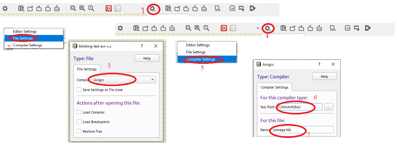
Click the gear wheel button "Settings" and click "File Settings".
Now select "Compiler: Avrgcc".
Click the gear wheel button "Settings" and click "Compiler Settings".
Click "Select tool path" and browse to "C:\WinAVR\bin" (or your path), click "Select Folder",
"Device: atmega168".
Then close "Compiler Settings" window.
Click "Compile", then click "UpLoad".
You should see
"Executing:
"C:/WinAVR/bin/avr-objcopy" -j .text -j .data -O ihex "C:/SimulIDE/examples/Micro/my-avr/blinking-led-avr-c/gcb_code/build_blinking-led-avr-c"blinking-led-avr-c.elf "C:/SimulIDE/examples/Micro/my-avr/blinking-led-avr-c/gcb_code/build_blinking-led-avr-c"blinking-led-avr-c.hex"
Whenever you want to edit a code you have to click the next buttons after changes: "Compile" and "UpLoad".
Then your program will work correctly.
Click the red button "Power Circuit".
You should see a blinking LED. -
Arduino has an AVR microcontroller inside. It can be ATmega328, ATmega168 or ATmega8.
We will prove it by creating our first Arduino program in Avrasm.
Blinking LED in Arduino Avrasm.
Create the folder "blinking-led-arduino-asm" in the directory "my-avr".
Create the subfolder "blinking-led-arduino-asm_ino" in the folder "blinking-led-arduino-asm".
Open the program SimulIDE and click "Save Circuit As", then save your project to the folder "blinking-led-arduino-asm\blinking-led-arduino-asm_ino" with the file name "blinking-led-arduino-asm".
Find (you can type a name of a component in the field "Search Components" or search a component by browsing Categories of Components in the left menu), drag and drop on Form the next components:
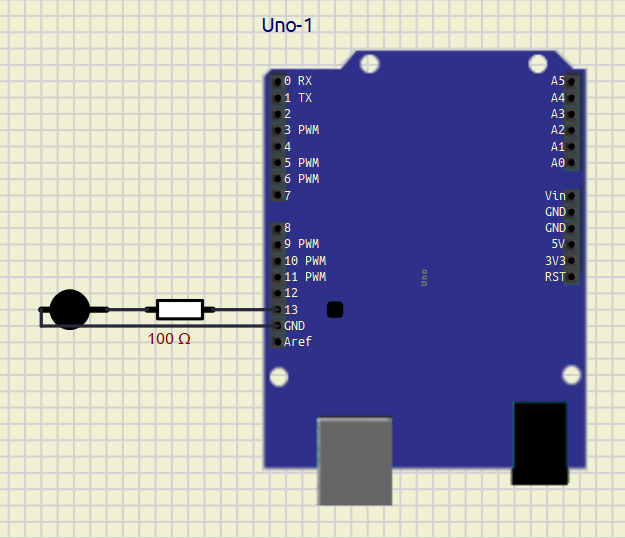
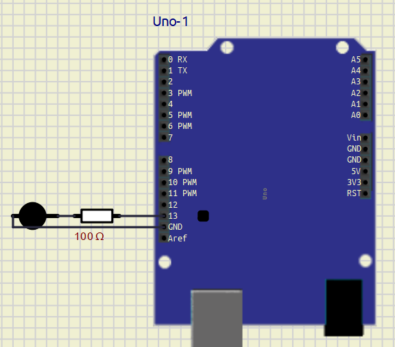
Arduino Uno (Micro->Arduino->Uno)
resistor 100 Ω (Passive->Resistors->Resistor)
Led (Outputs->Leds->Led).
You can zoom in/zoom out your working area by using a scroll wheel.
Connect all components with wires in the same way, as in the picture. You can rotate a component by right-clicking a component and clicking "Rotate CW/Rotate CCW" a few times. The resistor must be connect to 13. Rotate LED and connect it to GND. Pay attention to LED, since it emits light only if it's connected correctly. The current must go from an anode to a cathode (LED will not emit light if you connect it in the opposite direction).
Click "Save Circuit".
-
Create inside the subfolder "blinking-led-arduino-asm_ino" the next files blinking-led-arduino-asm.ino, blinking-led-arduino-asm.S using Notepad.
1.Open Notepad
2.File->Save As... and browse to the subfolder "blinking-led-arduino-asm_ino"
3.File name: blinking-led-arduino-asm.ino (blinking-led-arduino-asm.S)
4.Save as Type: All Files
5.Click SaveCopy-paste the next code to files
blinking-led-arduino-asm.ino/* blinking-led-arduino-asm.ino Blink an LED on pin 13 every 250ms using assembly routines. │Take a look at blinking-led-arduino-asm.S │ */blinking-led-arduino-asm.S
;blinking-led-arduino-asm.S
; Blink LED on PB5(Arduino Uno pin 13)
#define __SFR_OFFSET 0
#include "avr/io.h"

.global main

main:
  sbi   DDRB, 5     ; Set PB5 as output

blink:
  sbi   PINB, 5     ; Toggle PINB
  ldi   r25, hi8(1000)
  ldi   r24, lo8(1000)
  call  delay_ms
  jmp   blink

delay_ms:
  ; Delay about (r25:r24)*ms. Clobbers r30, and r31.
  ; One millisecond is about 16000 cycles at 16MHz.
  ; The inner loop takes 4 cycles, so we repeat it 3000 times
  ldi   r31, hi8(4000)
  ldi   r30, lo8(4000)
1:
  sbiw    r30, 1
  brne    1b
  sbiw    r24, 1
  brne    delay_ms
  ret
Open blinking-led-arduino-asm.ino in SimulIDE.
Click "Compile", then click "UpLoad".
Click the red button "Power Circuit".
You should see a blinking LED.
The pin 13 in Arduino is the same as PB5 in AVR microcontrollers.
We will not comment much this project, since it was made only for a demonstration. -
Blinking LED in Arduino.
Now we will create an Arduino project using a sketch. A sketch is the name that Arduino uses for a program. It's the unit of code that is uploaded to and run on an Arduino board.
Create the folder "blinking-led-arduino" in the directory "my-avr".
Create the subfolder "blinking-led-arduino_ino" in the folder "blinking-led-arduino".
Open the program SimulIDE and click "Save Circuit As", then save your project to the folder "blinking-led-arduino\blinking-led-arduino_ino" with the file name "blinking-led-arduino".
Find (you can type a name of a component in the field "Search Components" or search a component by browsing Categories of Components in the left menu), drag and drop on Form the next components:
Arduino Uno (Micro->Arduino->Uno)
resistor 100 Ω (Passive->Resistors->Resistor)
Led (Outputs->Leds->Led).
You can zoom in/zoom out your working area by using a scroll wheel.
Connect all components with wires in the same way, as in the picture. You can rotate a component by right-clicking a component and clicking "Rotate CW/Rotate CCW" a few times. The resistor must be connect to D0. Rotate LED and connect it to GND. Pay attention to LED, since it emits light only if it's connected correctly. The current must go from an anode to a cathode (LED will not emit light if you connect it in the opposite direction).
Click "Save Circuit".
-
1)int led=13; //creates variable led:=13
2)
3)void setup(){
4)pinMode(led, OUTPUT); //makes the pin 13 an output
5)}
6)
7)void loop(){
8)digitalWrite(led, 1); //writes the HIGH value to the digital pin 13
9)delay(2000); //delay 2 seconds
10)digitalWrite(led, 0); //writes the LOW value to the digital pin 13
11)delay(2000);
12)}
The function setup() is run only once and used for the initial setup.
The function loop() is an endless loop.
The setup function is a great place to initialize input and output pins so they are ready to be used. Then the program moves to the loop function code. -
int led=13; //creates variable led:=13 void setup(){ pinMode(led, OUTPUT); //makes the pin 13 an output } void loop(){ digitalWrite(led, 1); //writes the HIGH value to the digital pin 13 delay(2000); //delay 2 seconds digitalWrite(led, 0); //writes the LOW value to the digital pin 13 delay(2000); } -
Create a new code file in SimulIDE. Copy-paste the program to the code window of SimulIDE (you may click the button Select All (from the previous post) and press Ctrl+С (to copy the code from the forum) and Ctrl+V (to paste the code)).
Click "Save". Then enter "File name: blinking-led-arduino", select "Save as type: ino(*.ino)" and click "Save" in the pop up window "Save Document As".
Click "Compile", then click "UpLoad".
Click the red button "Power Circuit".
You should see a blinking LED.
Hello! It looks like you're interested in this conversation, but you don't have an account yet.
Getting fed up of having to scroll through the same posts each visit? When you register for an account, you'll always come back to exactly where you were before, and choose to be notified of new replies (either via email, or push notification). You'll also be able to save bookmarks and upvote posts to show your appreciation to other community members.
With your input, this post could be even better 💗
Register Login1 - 2025-01-27
2 - 2025-01-26
3 - 2025-01-25
In 2024, the number of babies born in South Korea increased for the first time in nine years. The change is welcome news for a country that is dealing with serious population problems.